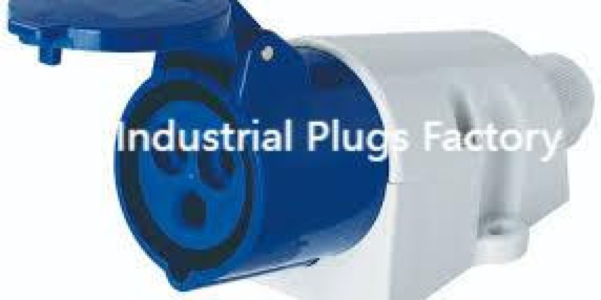
In heavy-duty installations the decision to specify a Industrial Plug early in the engineering process — and to select the correct variant judged against vibration, ingress, and thermal duty — often determines whether a circuit runs reliably or becomes a maintenance hotspot. Placing the right Industrial Plug where mechanical shock, washdown, or frequent mating cycles occur reduces field failures, simplifies spare management, and improves technician safety. This article examines design trade-offs, installation details, and lifecycle practices that help teams choose and maintain robust plug systems for demanding industrial applications.
Defining the application profile before specification
Begin by documenting the operating environment. Note ambient temperature ranges, exposure to liquids or chemicals, expected frequency of plug/unplug cycles, and whether the location is subject to impact or vibration. A precise profile narrows acceptable families of devices and avoids both over- and under-specification. For example, a zone requiring frequent washdown needs seals and finishes that tolerate cleaning chemicals, whereas a high-vibration mounting area benefits from retention systems that prevent micro-motion and fretting. Clear requirements reduce surprises during commissioning and lead to better spare-part strategies.
Mechanical mounting and retention strategies
How the receptacle or body is fixed to a panel or machine matters as much as its internal contacts. Rigid backing plates or reinforced mounting bosses reduce distortion of thin sheet panels and keep terminals from loosening. Where machines transmit shock, designers should incorporate vibration-damping mounts or captive-thread inserts. Consider the retention style—bayonet collars, threaded collars, or positive-latch systems—based on the likelihood of accidental disengagement and the ease-of-use expected by operators. Proper mechanical detailing preserves contact integrity and minimizes arcing risk created by intermittent connections.
Contact metallurgy, current capacity, and thermal behavior
Contact materials and surface finishes determine long-term electrical performance. Copper alloys with silver or specialty platings resist fretting corrosion and maintain low contact resistance through many mating cycles. Check contact face area and spring pressure against continuous current and expected temperature rise; insufficient contact area concentrates current and produces hotspots. For high-current applications, consult vendor derating curves at elevated ambient temperatures. Designs that allow replacing contact inserts extend service life by permitting targeted repairs rather than whole-assembly replacement.
Sealing, cable entry, and maintainability
Ingress protection depends on gasket geometry, gland selection, and flange compression more than on a single IP number. Compression gaskets with even clamping outperform thin adhesive foam seals over repeated maintenance cycles. Select cable glands sized to actual jacket diameters and position entries to avoid water pooling. Internally, separate power, control, and signal conductors to simplify troubleshooting and reduce electromagnetic interference. Design for service by using labeled terminal blocks, removable mounting plates, and standardized fasteners; these features shorten field repairs and reduce the chance of installation errors.
Installation practices and commissioning checks
A disciplined commissioning routine prevents many early-life failures. Verify part numbers and ratings on site, confirm correct pinouts, and torque all terminations to specified values. Perform insulation resistance testing and a thermal scan under realistic load to identify hotspots before the system is handed over. Schedule a short follow-up inspection after the first week of operation to re-torque fasteners and check gasket compression that may have shifted during initial thermal cycling. Document installation parameters so future maintenance is consistent and repeatable.
Monitoring, diagnostics, and preventive maintenance
Integrating simple monitoring at critical connections turns reactive repairs into planned maintenance. Periodic resistance measurements or thermal inspections can reveal rising contact resistance indicative of wear or contamination. For mission-critical circuits, consider inline sensors or IoT-enabled modules that transmit temperature or humidity alerts to maintenance teams. Establish replacement intervals keyed to duty cycles rather than calendar time—high-mating connectors or those in harsh environments should be examined and replaced more frequently to avoid unexpected outages.
Procurement, spare strategy, and lifecycle cost control
Total cost of ownership depends on predictable spare-part planning and vendor transparency. Favor connector families that offer modular inserts and common spare kits so a worn contact can be swapped quickly. Require manufacturer test data for performance claims—thermal derating, cycle endurance, and corrosion resistance—and include these metrics in bid comparisons. A small onsite kit with inserts, gaskets, and critical fasteners often bridges lead times and prevents extended downtime during repairs.
When teams treat power interconnects as system elements rather than throwaway parts, they gain reliability, safety, and lower lifecycle expense. Thoughtful specification informed by real site conditions, careful mechanical design, measured commissioning, and a proactive spare strategy together keep circuits operating and maintenance predictable. For technical details, selection guidance, and further references, see https://www.nante.com/news/industry-news/what-is-industrial-plug.html


